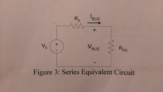
The purpose of this experiment is to make an electric circuit that can make the loads work properly when the power supply is unregulated. Our goal is to find the values for Vs and Rs that will guarantee that the bus voltage will stay 5.75V < Vbus < 6.25V when R1 = R2 = R3 = 1K and one of the three loads may be on anytime.
We want at least one switch is closed so the circuit can be simplified down to a series circuit.
Step 1: Design Calculation
a) Determine the maximum and minimum values possible for Req .
Req,max = 1 KΩ
Req,min = 1/3 KΩ
b) Since Vs and Rs are fixed, Vbus, max = 6.25 V ↔ Req, max
Vbus,
min = 5.75 V ↔ Req, min
c) Derive equation for Vbus:
and equations for the maximum and minimum bus voltage:
d) Simultaneously solve the equations above for Vs and Rs :
Vs = 6.53 V and Rs = 0.045 KΩ.
e) Using circuit analysis, determine the resultant maximum and minimum bus current:
Ibus, max = Vs / Rmin = (6.53
V) / (1/3 + 0.045) = 19.2 mA
Ibus, min = Vs / Rmax = (6.53
V) / (1+ 0.045) = 6.25 mA
Step 2: build the circuit and measure the components
Color code
|
Nominal value
|
Measure value
|
Wattage
|
Brown black black brown
|
1 K Ω
|
980 +/- 1Ω
|
1/8 W
|
Brown black black brown
|
1 K Ω
|
985 +/- 2 Ω
|
1/8 W
|
Brown black black brown
|
1 K Ω
|
983 +/- 1Ω
|
1/8 W
|
Resistor box
|
45 Ω
|
45 +/- 1 Ω
|
1 W
|
Data:
Config
|
Req ( Ω)
|
Vbus (V)
|
Ibus (mA)
|
Pload (mW)
|
1 load
|
980 +/- 1
|
6.09 +/- 0.01
|
6.1 +/- 0.1
|
37.149 +/- 0.67
|
2 loads
|
495 +/- 1
|
5.69 +/- 0.01
|
11.4 +/- 0.1
|
64.886 +/- 0.68
|
3 loads
|
327 +/- 1
|
5.33 +/- 0.01
|
16.1 +/- 0.1
|
85.813 +/- 0.69
|
a)
Example calculation for the 2 Loads configuration:
Example calculation for the 2 Loads configuration:
P= I*V = (5.69 V)*(11.4 mA) = 64.886 mW
Uncertainty: u =(0.01/5.69 + 0.1/11.4)*64.886 = 0.68 mW
b)
% up = (6.09 - 6.00)/6.00 = 1.5%
% down = (5.33 - 6.00)/6.00 = 11.16%
The values are different than the nominal value 5% because there could be some errors in the experimental procedure. We have to consider the uncertainty of measurement, the resistance in the wires and power supply, and the power supply may not stay as staple when it is moving.
c)
Keeping Vs and Rs the same, and add the fourth 1KΩ load in parallel. What would be the new load voltage?
Vbus, max = 6.25 V because the maximum resistance is always equal to 1kΩ.
Vbus, min = 5.53 V because the minimum resistance is equal to 1/4 kΩ now.
d)
The load voltage variation is 1% which means 5.94 V < Vbus < 6.06 V.
The new source parameters are Vs = 6.11V and Rs = 8.3 Ω


No comments:
Post a Comment